I have a MIMO 802.11g router, and USB wireless adaptor.
range is insufficient.
I measured signal to noise ratio in netstumbler on the comp with the usb thing. It went from -85dbi to -95dbi and disconnected (dunno if was db or dbm or dbi ). But apparently that indicates the outcome of signal strength /power over the distance (and there's no other easy way of measuring signal level or power). What is a good value for that signal to noise ratio?
I read that USB wireless has a rubbish internal "chip" antenna , and that makes for small range. I have one and it doesn't go past 2 flights of stairs.
I'd like a wireless 802.11g MIMO PCI Card, that comes with a reasonable antenna, but i'd also like it to have a connector for an antenna. (so I only have to buy an external antenna if it's not good without one).
Changing the router isn't an option at the moment.
(I did try pointing the aerials, including so the length of the aerial as oppose to the tip, faces the wireless usb adaptor, but no use. I didn't try moving the wireless usb adaptor around on a usb cable. I don't plan on getting a wireless usb adaptor with an antenna, but I might)
I'd like to know the power of these things before buying.. I've heard that Buffalo make powerful wireless stuff. But they don't seem to have any PCI, and I can't see the power rating.
(the buffalo website is a silly design anyway. each irrelevant picture links to a directory, the directory's name reveals what it's about. - so if you ever want to browse it, that's the way!)
I know linksys show power rating, but a few have recommended buffalo.
Didn't find your answer? Ask the community — no account required.
J
Jeff Liebermann
" snipped-for-privacy@yahoo.co.uk" hath wroth:
You have a problem. Let me know when you are able to read the label and supply the vendor and model numbers of your inadequate equipment.
So are your expectations. Could I trouble you to describe what manner of range you were expecting? Over what terrain? Through how many walls?
It depends on the connection speed. For a BER (bit error rate) of about 1 error in 10^5 bits, or about 10% PER (packet error rate): Speed SNR(dB) 11 6.99 5.5 5.98 2 1.59 1 -2.92 54 24.6 48 24.1 36 18.8 24 17.0 18 10.8 12 9.0 9 7.8 6 6.0 See:
for an explanation. What I managed to leave out is that these figures are for a fairly lousy error rate. One needs to add in the anticipated fade margin to get real numbers. Add about 20dB to each of the SNR numbers for what is considered "good values" for viewing with Netstumbler.
My stairs do not fly. You're correct. USB dongles have very small antennas. Antenna gain is very roughly proportional to the size of the antenna. The tiny chip or PIFA antennas have a gain of about
-6dBi to optimistically 0dBi gain. A typical non-MIMO PCMCIA card will have an antenna gain of about 2dBi, but it's rather directional.
Please note that your flight of stairs implies that you have a change of vertical elevation and that you might be going through a floor or ceiling. The pattern from the USB dongle is a close approximation of a hemisphere, so orientation isn't terribly important. However, that's not the case with the typical access point vertical coaxial antenna, especially if it's an add-on higher gain antenna. These trade gain in the vertical and horizontal direction (i.e through the floor and ceiling) in trade for more gain in the horizontal direction.
Forget it for now. MIMO functionality relys heavily on the matching between 3 or more antennas. As a result, an external antenna would need to have 3 antennas, 3 coax cables, and 3 connectors. There are some with external antennas, such as Linksys WMP300N but they're all PCI cards, where there's no other alternative to locating an antenna. All the other clients and access points have non-removable antennas or internal antennas.
Change what router into what? If you're going to practice enchantments and transmogrification, perhaps a practicing wizard or alchemist would be more helpful.
Indecision is the key to flexibility.
The transmit power is usually specified on the manufactories data sheets. If that's not available, it can be found on the FCC ID search page under the type certification test data. Buffalo makes various models. The WHR-HP-G54 transmits up to 250mw. 50mw is the default value.
Right. The product quality must be directly related to the quality of the web site.
Both manufacturers have their benefits and detriments. I don't want to go into a point by point comparison. See:
for reviews and comparison charts.
Incidentally, there may be some confusion here when using the latest MIMO buzzword. In the context of this discussion, there are 3 types of MIMO.
Airgo (Qualcomm) based chipset which in my opinion is "true" MIMO.
Ruckus Wireless based chipsets, which are basically beam steering, beam forming, or antenna aiming systems.
Gross misuse of the MIMO term by Buffalo on the WHR-HP-G54 claiming "MIMO like performance" with having any features that even remotely involve MIMO technology.
J
Jeff Liebermann
Jeff Liebermann hath wroth:
Duh. I forgot that Netstumbler does its probe requests at the slowest speed (1Mbit/sec). Therefore, the wireless speeds do not enter into the puzzle when using Netstumbler. However, if you are looking at the SNR reported by the wireless client, it should match the table plus about 20dB. The way the access point operates is to adjust the speed so that the error rate is reasonable. I'm not sure of the exact target value, but I think 20dB is about right. If the error rate creeps up, then the access point slows down the wireless speed to compensate. Therefore, with the access point speed set to "auto", you should always see about 20dB or better SNR.
I guess about 20dB would be a good minimum SNR for 1Mbit/sec with Netstumbler.
J
Jeff Liebermann
Jeff Liebermann hath wroth:
Perhaps I'll get it right on the 3rd try. (At home today with a fever and mild cold. Brain is currently somewhat malfunctional).
So far, that's correct. The access point adjusts the speed so that the *error rate* is constant, not the SNR. The SNR will vary with the connection speed.
I'm not sure of the exact target value, but I think a BER of about
1*10^6 is about right.
Therefore, with the access point speed set to "auto", you should always see 6dB to perhaps 40dB or better SNR depending on wireless speed.
D
dold
I don't agree.
J
Jeff Liebermann
snipped-for-privacy@90.usenet.us.com hath wroth:
Picky, picky. Ok, maybe not so good an approximation of a hemisphere. The basic idea is that the smaller the antenna, the better approximation of a hemispherical radiator it appears. The bigger PIFA antennas will be more erratic. Of course, there's a big hole in the direction of the dongle and cable.
Here are some realistic chip antenna patterns:
Yech. Ok, I give up. Something kinda sorta roughly vaguely resembling a hemisphere.
D
dold
Which way are you suggesting that the hemisphere is oriented? I always thought that you were picturing a hemisphere over the top of a dongle, with the cable exiting the bottom. That would mean the cable would be the nonexistent hemi of the sphere.
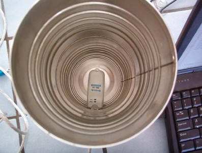
Those are the kind of lumps I see from signal strength measurements, except that I didn't see an equal back lobe. Putting that chip antenna on one side of a coper plated board might have a different signal pattern that the theoretical chip in space. The signal seemed to be moderately directional off the face of the dongle. Out the front of the can in my photo, if the can weren't there.
formatting link
J
jameshanley39
I will. But the reason why I didn't say, was because suppose at another point I have to fix a different model for a friend, then the knowledge here isn't much use, isn't transferrable.
if the answer here only applies to one model. Or applies to some models and not others, then I wouldn't know why.
router it is, of the types you mentioned.
But I don't know how to ascertain it, so I have to tell you the exact model numbers. I hope that's the case anyway. I like to know how to solve it myself. Not to just say here's all the information, you tell me the answer. Otherwise faced with a similar situation I wouldn't know. Also, this is all archived, so others can benefit if the explanation isn't tailored to me.
Belkin wireless G+ MIMO router (it has 2 antennas) Belkin F5D9230-4
formatting link
Belkin wireless G+ MIMO USB adaptor Belkin UK F5D7050uk
formatting link
2 flights of stairs.. All indoors. I haven't really measured. It's a friend's house.
So -80 to -95 is pretty bad!!!!!!
I know somebody that is happy with his -40 !
My connection was working at -85, then went down to -95 and disconnected.
sounds like the antenna is some kind of ecomonist.
I was told that they work like this
So I see how your description might fit that technical fact. But the person that told me that technical fact said I could orient it such that the side of it instead of the tip, faces the wireless adaptor.
So why does your tradeoff statement matter?
Anyhow, for some reason, reorienting both antenna so instead of the tip facing the wireless usb adaptor, the side did, it didn't help.
So is a PCI card with one antenna is as good as without an antenna? Is a PCI card as bad as a USB adaptor?
I heard that a MIMO router, MIMO is optional. The client may not connect using MIMO.. e.g. or i.e. If it's not a MIMO adaptor.
What if the adaptor isn't MIMO? It could have one really good antenna attached. Couldn't it?
It's an expression. It means returning it, selling it, throwing it out, discarding it, not using it. And replacing it with a different one.
It's an option. And sometimes it's the best option.
For example. Suppose you have a MBRD that breaks, you change it for another one.
In computers, when things don't work, it helps to change those things for something else that works or works better.
Or at least recognise that as an option.
I want to know all my options. And if that's too general a question for you, then the most important thing, is in particular, how far I can go with the PCI adaptor.
Are you implying that MIMO needs 3 aerials , else it's as good as no aerials?. And that the same goes for the adaptor that connects to it?
a wireless PCI adaptor with an external aerial is a waste of time. 'cos it's MIMO.
is a MIMO PCI adaptor without 3 aerials as bad as a Wireless USB adaptor?
What if that adaptor isn't MIMO? Can't the router choose not to use MIMO. And so your implication doesn't apply. One aerial , is succeeded by 2. Or I could have one powerful aerial.
what should I be be looking at to get an idea of strength of signal, and range.
dbi? or mw?
what numbers?
I never said it was. The product quality may be good, so all the more reason why it helps to have a tip on browsing the poorly designed site.
ok
ok!!
thanks for the list.
I guess i'd have to google and read more of something to ascertain which type a MIMO router is. But i've mentioned my model.
J
Jeff Liebermann
" snipped-for-privacy@yahoo.co.uk" hath wroth:
Most range and performance problems can be generalized. There's a bit on the topic in the FAQ at:
The usual problem is unrealistic expectations based on overly optimistic manufacturers promises.
However, if you're having problems with a specific model router, specific model client, in a specific location, with specific expectations, methinks this is not the appropriate place for a general course in RF propagation. In addition, there are at least radically 3 different types of MIMO and one vendor with MIMO hype, to add to the confusion. Each has its own propagation and preformance issues.
I would be elated if you would or could understand what I posted (and corrected twice). Some of it doesn't apply to different models, but you have to know what's inside and how it works. I really don't want to write an industry wide technology survey.
How to ascertain the type of MIMO you have:
Find the FCC ID number on the serial number tag.
Go to the FCC ID web pile and inscribe the FCC ID into the search page grantee code and product code. If it doesn't work, add a "-" in front of the product code.
Go to the internal photos and extract the part number of the chipset.
Go to the chipset manufacturers web pile and lookup the specifications and application notes on the chipset.
Also check the wireless product reviews at:
Perhaps you didn't notice, but my initial reply was NOT anything resembling an answer. That was due to your unwillingness to supply sufficient information to calculate an answer. What I supplied was the generalized theory of how such things work.
Looks like Airgo "TrueMIMO" Pre-N chipset.
Ummmm.... where does it say MIMO on the USB data sheet? It's not a MIMO USB adapter because it only has one antenna. It will work with a MIMO router, but there's nothing MIMO about the basic product.
Are you sure it's not a F5D7050? The US version is MIMO:
No clue who's chipset is inside. Check on FCC ID web site or post the FCC ID and I'll do the digging.
If you can't measure, try guessing. Also, you didn't answer the question. What range were you expecting and going through what manner of interior construction material? See list of losses in the FAQ at:
If you are trying to penetrate some of the high attenuation materials, you're not going to go very far, with or without MIMO.
Not exactly. That's the noise level, not the SNR (signal to noise ratio). Netstumbler gives two numbers. Signal level and Noise level. If you subtract the two, you'll get SNR. Unfortunatly, it's somewhat subjective.
For example, see:
and note the Netstumbler screen capture. The left part is about
-85dbm signal, and -95dBm noise for a SNR= 10dB. The right part is about -67dBm signal, and -98dBm noise for a SNR= 31dB. However, the Orinoco client manager says SNR= 16dB, which is nowhere near either result. Oh well.
Which went down? The signal or the noise? Using Netstumbler or something else?
True. There's no such thing as a free lunch or free antenna gain. A higher gain antenna trades beam width for gain. It also trades VSWR bandwidth, but that's a different problem.
The side of what antenna?
Easy. Your Belkin access point has the bulk of its gain and therefore it's range in the horizontal plane. If you try to connect with something that is above (or below) the horizontal plane, you're going to see less gain.
As the antennas cannot be replaces on the Belkin access point, there's no point in going into the effects of increasing their gain in order to possibly improve performance. However, if they could be replaced, then you would get more gain and range in the horizontal plane, and less gain and range vertically (i.e. up your stairs).
As good as compared to what? MIMO generally has better range because it tolerates reflections better than ordinary 802.11g. Depending on what speed you're expecting, range will be better with ordinary
802.11g speeds. The PCI cards generally have much better antennas than USB and will therefore be correspondingly better. In general, the bigger the antenna, the better it works.
Generally true. You can turn it off in the access point and you'll end up with the equivalent of an ordinary 802.11g access point. You might also have to turn off some of the other proprietary enhancements such as turbo-G, afterburner, burst mode, 125Mbits/sec, etc.
Correct and your Belkin F5D7050uk is not a MIMO client. However, the F5D7050 is a MIMO client adapter:
Yes, it could but it's unlikely that anything crammed into a USB dongle enclosure has a decent gain antenna. Even with MIMO, a crappy antenna works badly.
Changing your expectations is another possibility. I don't have enough info to recommend anything specific. However, I can tell you that when the signal gets weak, *ALL* (and I do mean *ALL*) the wireless access points reduce speed in an effort to improve sensitivity. Once that happens, all the MIMO, turbo-G, super-G, whatever enhancements are effectively disabled. Range and speed can be traded for each other.
Sure, but that's an expensive way of troubleshooting. I'm partial to defining requirements, understanding the technology, and selecting something reasonable based on these. There's also a problem with "works better". That's fine, but the not necessarily universal for all environments and applications. For example, different technologies do better for reflective environments, long range, video, large numbers of users, coffee shop environment, outdoors, indoors, and such. My guess is they're all about 85% identical, but the last
15% is what provides the product differentiation.
Replacement is always an option. I'm just suggesting that you not do it randomly or in an uninformed manner.
That's actually easy to calculate. The problem is that your unspecified indoor arrangement is a key part of the puzzle. I also need to know what speed you're expecting (speed and range can be traded). I've done the calculations for outdoor links many times in this newsgroups. For example:
Aim for a 20dB fade margin. Specs can be scraped from the manufactureres data sheets. If you have problems, post your numbers and I'll try to help.
Ruckus MIMO is actually a steerable single antenna. Usually, it's a big circuit board antenna inside the wireless router. No external antenna needed or possible.
True MIMO must meet the 802.11n preliminary specifications, which requires 3 antennas.
Airgo has an oddity which isn't really MIMO because it doesn't meet the 802.11n specification, but which combines two streams. It acts like MIMO, but uses only two antennas. That's your Belkin:
I don't think you'll want a PCI card with an internal antenna. The RF won't make it outside the metal box. With PCI, it has to be external.
A MIMO PCI adapter, with no antenna, is not going to work. I don't see what you're asking.
A non-MIMO client can connect to a MIMO router without difficulties. The MIMO routers are all downwards compatible.
Please understand that two antennas are not twice as good as one, or three antennas are not three times as good as one. The only thing the multiple antennas do for the system is deal with reflections and their position, allow for combining data streams to get more speed.
Good question. I think a benchmark test is in order. Download IPerf from:
Plug a fast PC into the Belkin wireless MIMO router using CAT5 ethernet cable. Run iperf as a server in a DOS window as: iperf -s On a laptop, connect to the Belkin router via wired or wireless. Run: iperf -c ip_address_of_server You should get some TCP thruput performance figures. Play with the options and arguements.
Now, move away with the laptop and check your thruput at different places in the house. Never mind signal strength, SNR, and such for now as these don't mean much when not moving data. Just range and performance. Walk around and you'll get a fair idea of how well your system covers the house.
If you have time and patience, try a line of sight test. Measure out a range and measure the thruput. It should be fairly constant and slowly dribble down to zero as you get to the extreme range.
Now, do the same thing with one big change. Change the wireless speed in the access point from "auto" to 54Mbits/sec. Do the walk test again. This time, it will probably be quite constant until you get to some threshold, where it will drop very quickly to zero. That's your maximum range at maximum speed point.
You'll find plenty of such graphs under various reviews at SmallNetBuilder.com.
dBi is antenna gain (over a theoretical isotropic radiator). mw is power output in milliwatts. Apples and oranges. Range is measured in meters. Performance in Mbits/sec. Signal strength and Noise level are in dBm or dB over 1 milliwatt. SNR (signal to noise ratio) is in dB which is a ratio.
J
Jeff Liebermann
snipped-for-privacy@90.usenet.us.com hath wroth:
Ummm... hemispheres don't have points. However, I get your point. My guess(tm) is that the maximum gain is in the direction opposite anything that might act as a reflector. Therefore, for a PCB mounted chip antenna, located near the narrow edge of the PCB, the maximum gain would be upwards from the chip antenna, and slightly forward. One thing for sure is that it's not symmetrical.
When the chip antenna is near the edge of the PCB, there's quite a bit of RF radiated in the downward direction from the bottom of the PCB.
It think the plots were done with a test board, which might not have construction similar to a USB dongle. My guess is that the USB dongle is far worse than the test board in terms of pattern symmetry.
It's certainly not done in free space. Usually, the data sheet mumbles something about a ground plane under the chip antenna for strip line antennas. For meandering 1/4 wave lines, no ground plane is desired. PIFA requires a ground connection, but no ground plane.
D
dold
A hemisphere certainly has an orientation. I didn't say points.
"upwards" requires clarification.
I gather that you are laying the dongle down on the table, with a cable running along the table, toward the PC. "Up" in that reference would be off the face of the dongle.
formatting link
If I took a half of a basketball, and set it open side down over this coffee can, would that represent the hemisphere of radiation? Or would the basketball sitting on a table be properly oriented if the dongle were sitting on it's connector, with the cable going down through the table.
Does the radiation flow in the same direction as the light from the little LEDs on this dongle?
Reflecting off the bottom of the can in my photo?
J
John Navas
On Thu, 03 May 2007 15:06:10 -0700, Jeff Liebermann wrote in :
Or downward. Or to the side. USB has no fixed orientation.
Antenna radiation patterns can be surprising. I just upgraded my ThinkPad T41 from modem card (not mini PCI) to modem+Bluetooth card. Too lazy and cheap to take the entire machine apart to install a factory antenna in the LCD assembly, and not needing anything like maximum range, I placed a small Hitachi mini antenna near the card and system memory slot at the back of the chassis under the keyboard (which has a metal backing plate). Works great -- I'm surprised at how good a signal I'm getting in different directions.
J
John Navas
On Thu, 03 May 2007 14:53:23 -0700, Jeff Liebermann wrote in :
Probably radiation to the sides of a vertical rubber duck antenna.
One antenna; i.e., not as bad as a standard USB dongle, but not all that much better unless it's a non-stock external. 'Course a few USB adapters can use better antennas too.
J
jameshanley39
Many thanks for writing such an informative post, in a style that was so useful.. Once I set up wireless at my home, i'll apply some of this analysis to it, look at the figures in netstumbler. Is orinoco client manager generic ?
In the case of my friend's router, I'll look at what I can while there, I will try a PCI card, I think even the USB wireless adaptor almost manages it, so a PCI card will reach fine. I will make better use of your post once I get things set up at home, and read up a bit more.. and analyse my home set up(s).
You were right, the USB adaptor I got wasn't MIMO.
one on the belkin wireless G router. Rubber antenna. It has 2.
But I can move the antenna from
ceiling >|< >|< >|< floor
to rotating the antenna such that the side of it is parallel with the ceiling and the floor. I've heard it helps. But oddly though, it made no difference. Or may have even caused a disconnect. If this was at my place, I could analyse it properly. I will experiemnt with similar things at my place when I get things set up.
and, I just realised.. a MIMO anything would have to have more than one antenna. If there's only one external one, just must be more internal ones. this one has 7 internal ones.
I'm looking at these 2 PCI cards as options. Either for my friend's system, or to have at home anyway.
NETGEAR PCI card WiFi 108 Mb MIMO WPN311
formatting link
(quite expensive from other places, but cheaper from there)
And this GIGAFAST MIMO WM730-PI, is dead cheap.. And has 3 external antennas. May not be a good make, but looks good! And has the 3 - external - antennas there
formatting link
Linksys provide more information than netgear.. in their data sheets
on linksys.com WMP54G
-transmit power 15/19dBm
-sensitivity -70dBm/-85dBm
-antenna 5dBi
It doesn't have a connector for me to add an antenna. But 5dBi doesn't sound bad.
One that does have connectors for external antennas is the WMP54GX RF power 18/16dBm, antenna gain 2dBi, (But it seems to have 3 connectors for antennas!)
2dBi seems low(I've heard good things about the 7dBi Hawking high gain omni-directional antenna). Maybe the antenna linksys refers to is internal. ?
But I also heard that an antenna that is too powerful can damage a card. What data do I look for to know if it's ok? (I know, i could ask the antenna manufacturer to just ell me if it's compatible)
J
Jeff Liebermann
" snipped-for-privacy@yahoo.co.uk" hath wroth:
Thanks. What I lack in content, I make up in style. Actually, I usually don't burn this much time answering questions. However, I have a cold or flu and am at home playing on the computah.
I'm becoming less and less a fan of Netstumbler. It's really useful for fairly simple comparisons between setups and antennas. However, it's not very good for detecting interference from other networks, since many do not bother to broadcast their SSID. For that, I use Kismet on a Linux LiveCD. No need to install Linux on the hard disk. The LiveCD will boot and run the mess of programs included. Logging can be done to USB dongle or floppy. I suggest Backtrack at:
However, before you dive in, make absolutely sure your wireless device is supported. Dig through the Wiki:
It's in there somewhere... ugh, by laptop, not card:
No way. It's non NDIS5 and talks directly to the Orinoco chipset. Worse, there are several radically different versions for different chipsets used by WaveLan/Orinoco/Lucent/Agere/Avaya/Proxim etc.
See if this does anything for you:
I was totally confused for a while. It seems that the US version is MIMO, while the UK version is not MIMO. They're also different colors, look a bit different, but have the same Belkin part numbers. I tried (and failed) to find the FCC ID for both. Then I realized that UK version don't care about US FCC type certification. Look on your serial number tag and see if there's an FCC ID number. I'm curious about the difference.
Yeah, that will move the major lobes of the antenna pattern in the up/down direction at the expense of horizontal coverage. However, the tiny vertical antennas don't have much gain and therefore don't have much of a radically directional pattern. You can get some improvement by "aiming" the access point, but I don't think it will help.
However, if you had purchased a more conventional wireless access point or router, with a single or dual diversity antenna system, you could have installed a reflector or aftermarket antenna to get more gain.
Well, then something else might be happening. If you have aluminium foil in the walls blocking the signal, no amount of antenna juggling is going to help. If the blockage doesn't kill the coverage, then the reflections might.
Huh? The Belkin wireless G+ MIMO router Belkin F5D9230-4
formatting link
an internal directional antenna as in the Ruckus Wireless MIMO system? Are you sure? Send me the FCC ID number (if any) and I'll check the photos on the FCC ID web pile.
Hint: When discussing multiple devices, kindly avoid using the terms "it", "this one", or other vague references. Try to be specific, even if it means being repetative.
Free advice. Don't bother with 108Mbit/sec, 128Mbits/sec or other speed related enhancements. You only get that speed over very short distances and with corresponding technology access points. However, if you're doing video or massive wireless file transfers, then the added speed is a good idea. Check the reviews on SmallNetBuilder.com.
Sorry. No experience with either the Netgear or Gigafast parts. I don't know what to suggest because you've twice avoided supply details of how and where it is to be used. Hint: Forget the descriptions and just supply the numbers. How far, how fast, how many?
Not really. That might happen with a 24dBi dish antenna in close proximity to another such dish, but not with common conventional rubber ducky and PCB antennas. It's also possible to overload the receiver front end from being too close or having too much antenna gain. The problem is not so much too much signal, but is also a timing issue. In general, you have to be a few feet away from the access point antenna for things to work correctly.
Do you really want the answer to that? It's usually not a consideration. However, I can give you a bad guess. Most receivers overload at about -10dBm input. Assuming 2dBi antenna gain and -2dB cable and connector loss, we're looking for what manner of transmitter and antenna will produce -10dBm at the rx input. Go to:
and plug in various values for the distance (in miles) until you get
-10dBm at the receiver input. Use +15dBm for tx power and +2dBi for antenna gain and -2dB coax loss. I get about 0.00025 miles or about
1.3ft. Yeah, that's about right.
J
Jeff Liebermann
snipped-for-privacy@90.usenet.us.com hath wroth:
Well, ok. However, I may have goofed using hemisphere for the description. Hemisphere means half a sphere, which the antenna pattern only roughly resembles. More correctly, the pattern should be described as "spherical" rather than "hemispherical".
Sorry. I tend to visualize the radio in its normal operating postion. That's easy with an access point or PCMCIA card, but rather ambiguous with a USB dongle. I'll assume that the long axis of the USB connector on a laptop is horizontally oriented, thus placing the PCB in the horizontal plane, and the chip antenna on the "top" of the board, oriented "upwards" or away from the table. I realize that some laptops have vertically oriented USB connectors, so my description doesn't always work.
Correct. However, without the coffee can.
I really don't know. Radiation patterns are generally calculated for the outside of the antenna (i.e. far field). I'm sure it can be calculated for the inside of the coffee can, I just don't know how it's done. The coffee can has a huge effect on the pattern.
Outside of the coffee can, the bulk of the RF goes in the direction of the mouth of the can from a point near the end of the USB dongle. I think this is what's inside:
The antenna is at the end with a ground plane on the "bottom" of the board. Therefore, I would assume that the bulk of the RF goes "upwards" and slightly forward (off the end of the USB dongle). I could probably model the combination, but I don't want to spend the time today.
Yes, but also from the ground plane on the bottom of the PCB. See photo. The catch is that it's not like a barrier to RF. With the antenna hanging off the end, lots of RF misses the ground plane and goes in the "down" direction. That gets reflected by the bottom of the can, reinforces the indicident wave coming directly from the antenna, and radiates out the mouth of the can. Even without the sides of the can, a simple reflector will offer gain.
J
Jeff Liebermann
John Navas hath wroth:
Yep. Equally lousy gain in all directions.
I just hate it when someone ruins perfectly good theory and calculations with reality. There's no way that sandwitching the antenna between two sheets of metal in the laptop should work. Yet, it does. It could be the card itself is leaking, or VSWR from the proximity of metal to the antenna is causing the coax cable to radiate. Dunno and just guessing.
I had a customer's Dell something laptop that had some service shop replace his bashed in LCD display with a replacement. They chose to replace the entire assembly instead of just the panel. Too bad the replacement didn't have the usual wireless antenna inside. Rather than do it correctly and order the proper antenna assembly, I just took a U.FL connector pigtail and peeled back about 3.1cm of shield to form a coaxial antenna. I insulated the mess with some shrink tube and crammed it into the guts of the laptop as close to the side as I could manage. Works just fine and no complaints.
It's all magic.
D
dold
Darn, I was starting to like the idea of a hemisphere, because my simple tests show that it does have a directional component. I don't think it resembles a full sphere.
"normal" requires clarification ;-)
Ah, oriented as if it were plugged into the laptop, not dangling from a cable. Okay. Now I have the picture, and your justification for that orientation. For "gain" applications, I would always have the dongle on a cable, maybe dangling from the rearview mirror of a car. I thought laying it on the table seemed odd. Plugging it into a laptop might be useful. ;)
It was the only picture I had ;-)
I think there is a directional component to the DWL-122. Just taping it to a wooden yardstick and holding it vertically, your "up" would be my "forward". I think it had a stronger front lobe than side lobes, not omnidirectional. Not much signal off the tip, and I don't recall getting much signal off the "back", but I might not have checked that much.
S
seaweedsteve
Going back to the orginal post, here's a smorgasboard of suggestions:
1) what are the materials between your AP and your PC? Do you have something blocking the signal so that it just won't work? A chimney?, concrete floors? If so, then use powerline ethernet adapters and work around the reception issue. You can even get sets that put an mini AP on the upstairs end so that you are still on WIFI if you need it for a laptop
2) Is your USB dongle on an extension? Have you tried other positions? Get a USB extension- 15 feet max and try that ! Really, finding the right location could make a world of difference.
3) Have you checked out the "USB cookware" idea? Google it. There is a group of people promoting this, where you put the usb dongle's antenna inside some commonly availible parabolic reflector (wok, chinese fry basket, etc) and it's supposed to increase gain. Your mileage may vary, but it's a cheap and easy solution to try.
A homemade relector could also do the job for your usb dongle. Google "EZ-12 reflector" Somebody on this forum has had good success with those and USB adapters. I've had success with those on rubber duck antennas. You could try it on your router too.
4) If you must buy something, I'm currently most excited about this device:
formatting link
It has increased sensitivity and transmit power over typical USB adapters.
And unlike PCI, it can be used on a laptop as well as desktop. Also more powerful than most pci cards it won't require lossy coax cable to get your antenna(s) out from behind the computer shield and, best of all, it has an EXTERNAL antenna connector with a 2dbi antenna included.
With probably 2-4X the power of a typical usb, plus an included antenna with typically > 2dbi over the built-in antenna in most usb adapters, this one should make a significant difference.
Oncue you get it, first try finding it's best location (using that 15' usb extension! ), then, if still not good enough, you can put an EZ-12 reflector on it's antenna, then it that's not acceptable, you can always put a cantenna, panel, yagi or grid antenna, whatever you want on it.
This baby looks like a great universal problem-solving tool for reception issues. And if you want to help a friend, you can take over this guy, along with a reflector and apply some fire-power to any poor reception issue on any computer with USB.
Steve
J
John Navas
On 4 May 2007 06:38:18 -0700, seaweedsteve wrote in :
I like the Hawking HWU8DD Hi-Gain USB Wireless-G Dish Adapter
I doubt it actually has increased sensitivity.
Without an add-on external antenna, the HWU8DD will stomp all over it, and even then, the HWU8DD might well give it a run for its money.
Join the Discussion
Have something to add? Share your thoughts — no account required.
Didn't find your answer?
Ask the community — no account required
Report Content
You are reporting this content to the moderators. They will look at it
ASAP.