I have an alfa usb radio RTL8187 from which I am able to connect to a public AP with a homemade antenna/reflector, but the throughput is slow and connection unstable.
I picked up one of these at a yard sale.
formatting link
(DWL-G710 High Speed 2.4GHz (802.11g) Wireless Range Extender) The router for the public hotspot is also a dlink, but I have no direct control over it.
Can I use this alone strictly as a client transceiver to get a better signal? Or in conjunction with the Alfa?
I have no home network, just a lone pc, no router. OS is WinXP.
Didn't find your answer? Ask the community — no account required.
J
Jeff Liebermann
Does it use WEP, WPA, WPA2, or no encryption? Although the data sheet claims that it will do WPA/WPA2, there might be some gotcha where it won't work as a store and forward repeater. Easiest way to be sure is to first update the firmware in the DWL-G710, and just try it.
Looking at the data sheet, there's no mention of using it as a client bridge. It kinda looks like it's going to be only a repeater.
I'm not a big fan of range extenders or repeaters. However, there are places where they will work. One of those conditions is where the client radio (your laptop) cannot directly see/hear the remote access point. This way, there's no way the laptop could attempt to directly connect to the access point. Everything has to go through the repeater. Depending on your situation, that may not be too easy to achieve.
If you need some entertainment, try this test. Drag your laptop and the range extender to somone's house that has an access point. (Don't do this at a coffee shop hot spot). With the range extender OFF, connect to the internet and run some kind of speed test, such as:
or maybe a local server running iPerf or Jperf:
Now, turn on the range extender (which is assumed to be correctly configured) and try the speed test again. I've seen some rather gastly deteriorations in performance. Turn the repeater off, and things work again. That's what happens when the client can hear the access point.
In my never humble opinion, you're better off with your USB dongle, and homemade antenna. If it's lacking in performance, get a better antenna. Incidentally, the uglier the antenna, the better it works.
D
Dr Who
I can't see how a repeater would be of any use in your situation.
I use the very same chipset adapter (8187L) with a cheap beam yagi (16 dBi) and this type of antenna should help a lot.
They work better than anything else I've tried for long distance (at low cost).
Dirt cheap - don't believe the 20+ dBi claims though.
eg.
formatting link
J
Jeff Liebermann
Put it on the roof top where it has a better view of the hot spot? However, you're right. A better antenna will do wonders.
I don't like yagi's. Details on request.
Same as:
Hopefully, this yagi is NOT the one you're currently using. It's not clear from your message if you have this yagi, or something else.
I recently bought two of these when the price dropped to less than the cost of the hardware.
I figured that it might be useful. So did a friend that bought one. Well, after much tinkering, we decided that it's a piece of junk and that the stock 2dBi rubber ducky works better. I don't have any numbers or test data, but when I have time, I'll do necessary testing and denunciations.
Notice the crude dipole under the plastic radome. No matching circuit. In the side view, notice how far the driven element is offset from the axis of the other elements. It can be off a little, but not almost 1/4 wavelength. This thing doth suck.
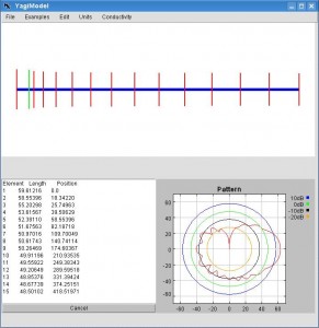
While we're on yagi's, I did an analysis of the MFJ-1800 yagi at:
It had a chance, but the designer apparently forgot to include a matching circuit. If you happen to have a 200 ohm feed, it should work. Otherwise, it has a minimum VSWR of about 4:1, which also doth suck.
Incidentally, in a perfect world, the maximum gain of a yagi antenna would be 1.66 (the gain of a dipole) times the number of elements. So, a 15 element yagi, would have a gain of: 10 * log (1.66 * 15) = 14 dBi
20dBi is science fiction as it would require 60 elements and a boom four times as long as the one in the eBay advertisement. Also, note that this is best case, and does not include any matching losses.
Duh, I just figured out another big screwup with this yagi. The designer forgot that when you have a big fat boom, the length of each element has to include the path travelled around the boom. For example, if the cut length on an element is 0.5 wavelengths, one starts measuring from the end of the element, AROUND the boom, and then to the other end of the element. Straight line won't work.
D
Dr Who
Wow Jeff, you really hate that yagi :-)
No, that's not the one I bought, but assumed they were all much the same.
Mine is a 15 element Ebay model and it works well.
I did some basic testing and it certainly did the job for me.
formatting link
I suppose it's a case of suck it and see.
Cheers
Rob
A
atec77
Why not cheap and work very well on hf work extremely well in stacks of vhf
A
alexd
Meanwhile, at the alt.internet.wireless Job Justification Hearings, Jeff Liebermann chose the tried and tested strategy of:
The directors don't seem to be insulated from the boom, from that picture.
J
Jeff Liebermann
The directors do NOT need to be insulated in order to work. However, if they are electrically connected to the boom, the circumference of the boom needs to be included in calculating their electrical length.
J
Jeff Liebermann
Short version (because I'm busy today).
Why Yagis suck:
Far too many side lobes and marginal front to back ratio. This is important when trying to reduce interference, and to obtain isolation from other systems on the same tower.
Lousy bandwidth for a given gain.
Too many parts making them difficult to build. A comparable panel or reflector type antenna is much easier to build/manufacture.
Excessive boom length to get usable gain. At 2.4GHz a 19dBi dish is about 1x2ft across. A comparable yagi is about 10ft long. A 24dBi dish is about 2x3ft across. A comparable yagi would be about 20ft long.
I now have 2 examples of yagis that don't work (MFJ-1800 and that eBay thing).
Somewhat excessive beamwidth compared to a dish. See chart below scraped from various data sheets and NEC2 models. Type Gain -3dB BW dBi degrees Biquad 10 60 Panel 19 18 Dish 24 8 Yagi 15 30 Dish 15 19 Coffeecan 8 60
Personal prejudice: In about 1980(?), I built a 1575/1691Mhz GEOS WEFAX system. Due to temporary insanity, I built a 25 ft long yagi antenna out of acrylic tubing pieces with fishing line guys for stabilization. The logic was that a yagi uses less roof space, and was more easily shipped than a dish. It barely worked, despite considerable expert advice and assistance. If learning what NOT to do is considered educational, this monstrosity was a classic example. I finally gave up and went back to a conventional dish, which worked the first time.
On the other foot, there are some benefits to using a yagi.
They make great foot pegs on a tower.
Birds love to sit on them (horizontally polarized or lower frequency only).
Ice sticks like glue to the elements.
They look cool.
Fits nicely in the trunk of a car.
Is easier to ship than a dish (but a panel is even easier).
J
Jeff Liebermann
I don't hate all yagis, just the junk that I keep blundering into.
If you're curious, I like Franklin/AMOS sector antennas. For example:
It's not suitable for connecting to a remote hot spot, but great for covering a wide area or sector.
Nope. At 2.4Ghz subtle differences can have a HUGE effect. The one in your photo uses a folded dipole driven element, which is typically about 200 ohms impedance. That can easily be matched to 50 ohms with a 4:1 balun or very careful selection of element spacing (with some loss in gain). The driven element is also in line with the rest of the elements. Yours looks much better built than the abomination that I purchased.
Nice web page and tolerable testing method. Without my pile of test equipment, I use a similar method. I take a reference antenna, with known gain and characteristics (8dBi patch antenna less coax losses), and compare the results. It's not hugely accurate but is cheap and easy.
Looks like exactly the same antenna as the one I bought, but with a different driven element. Also looks like a much longer and better coax cable. My guess(tm) is that someone borrowed the design, and then cost reduced it with a much cheaper driven element. Maybe I'll buy one with a folded dipole driven element and compare.
Also looks like yours with the added bonus of an even more inflated gain claim. While an ideal 15 element theoretical yagi might have about 14dBi gain (at best), this eBay wonder claims 25dBi.
Yep. For what little it costs, it was easy enough to buy and try.
D
Dr Who
Jeff, Looking at the schematic of the MFJ-1800 on your link, I noticed it suggests that all the driven elements are equally spaced.
Is that correct?
On my cheap yagi they vary in a virtual wave pattern.
While I haven't built a yagi, I notice that the DIY designs have variable element spacing as well.
What gives ?
A
atec77
verbiage snipped , so you dislike them at uhf and above , cant argue that although they have their place agreed there are better in the range (still good where I mentioned)
D
Dr Who
OOPs Jeff, I meant to say all the "elements" are equally spaced (only one driven).
J
Jeff Liebermann
All except the reflector.
Since I wrote it, it must be correct.
That's just plain sloppiness in constructions. There are yagis where the spacing is different between elements, but once you get past about the 3rd director, equal 0.2 wavelength spacing is what works best for maximum gain. If you optimize the antenna for minimum side lobes, it usually requires some variable spacing, but not past the 3rd director.
Try it and see what you get (busy tonite):
Sure, but they never vary in a "wave" pattern.
Dunno. Show me an example of a long boom antenna with this wave pattern.
Incidentally, one of my friends noticed that the elements were not in the center of the boom, which is the traditional construction method. See photo at:
The problem is that the element length must include the boom and if there are two lengths to the boom, the models start to fall apart. I have no clue what the effect of such an asymmetrical construction might be, but it can't be anything good.
J
Jeff Liebermann
Ok, I'll bite. Ever rotate your HF yagi and find that the DX signal is equally strong from all directions? I've seen this many time, and often wondered if the antenna was broken or misdesigned. There was an article in a recent QST explaining the phenomenon. It seems that ionospheric refraction does NOT require that the angle of incidence is equal to the angle of reflection. Most commonly, they're quite different, resulting in the signal coming from directly overhead. (No, this is not NVIS). The author offered an experiment using WWV to demonstrate the phenomenon. I didn't try it, but one of my friends did, and verified this contention. So, with the signal coming from directly above, what good is a directional HF yagi?
J
Jeff Liebermann
They do NOT need to be insulated from the boom. However, if they do connect to the boom, the calculated element length must include the outside circumference of the boom (which it apparently does not). Also note that the MFJ-1800 yagi is one solid piece of stamped sheet metal, which also does not insulate the boom.
A
atec77
rarely I've seen this many time, and
has to do with arrival angles as we know
There was an
most of the time gain delivered means not needing the amplifier and rx gain is worth while as you know I guess you don't like quads then ?
>
D
Dr Who
The elements in my Chinese yagi are also the same - not in the centre.
Mine works OK as per the test results, but what effect that has, I have no idea.
The yagi below uses variable element spacing, as previously mentioned.
formatting link
Rob
D
Dr Who
Here's a better link.
formatting link
A
atec77
I made my own from the junk box a while back , some 3mm wire 10 mm round tube and a tig , works fine
Join the Discussion
Have something to add? Share your thoughts — no account required.
Didn't find your answer?
Ask the community — no account required
Report Content
You are reporting this content to the moderators. They will look at it
ASAP.