's not a parabolic reflector. It's circular or rather part of a circle. The circular shape reflects back on itself resulting in a not very directional but also not totally useless antenna pattern. I'll model it with 4NEC2 when I stop chuckling. I guess I should also do some gain testing.
Of course, the aluminum reflector can be bent easily into something resembling a parabola. Well, maybe not so easily as it's fairly stiff. $8 at your local camping store. Mounting contraption included. Coleman 295A720T. |
formatting link
Didn't find your answer? Ask the community — no account required.
R
Rich
I have two antennas on my linksys. Is one side transmitting and one side reciving? Or will one side tx & rx, Can I use this and beam one side to my frieind
formatting link
J
Jeff Liebermann
"Rich" hath wroth:
What model Linksys is connected to your two antennas? WRT54G?
Each antenna is part of a diversity reception system. The Broadcom chipset in the Linksys WRT54G will select which antenna heard the last good packet received. When selected, it is used for both TX and RX. You can control which antenna is being used with alternative firmware, but not the stock Linksys WRT54G firmware.
At one time, there was a problem with pointing one antenna to the neighbors and using the other for local coverage. It would only appear when transfering large files between the two wireless connections. I'm fairly sure this is no longer a problem on current Broadcom chipsets.
If you use two different antennas (or one reflector) you effectively break the diversity algorithm. There's a really good chance that the router will select the wrong (weaker) antenna based on simple probability as to which antenna happens to be active when a packet arrives. If it's the weaker antenna, then you will have rotten signal reliability until the signal completely disappears and the router decides to scan for a better antenna. Someone found a nifty article explaining the problem of using different antennas, but I can't find it.
Before you spend $8 on an obvious abomination, you might look at:
formatting link
formatting link
is a much better design.
R
Rich
BEFW11S4
formatting link
R
Rich
I am trying to get a 1/4 mile to a wusb54g
formatting link
W
William P.N. Smith
Not going to happen, get a pair of WAP54G devices and some gain antennas and you might be able to bridge things...
J
Jeff Liebermann
William P.N. Smith hath wroth:
Agreed. The Coleman lantern reflector might gain about 6dBi at best. Without additional gain at the WUSB54G end, it won't work. See the FAQ for link calculations at: |
formatting link
guess is: TX power = +15dBm (at BEFW11s4 end) TX coax loss = 0dB TX ant gain = 6dBi (lantern reflector) Distance = 0.25 miles RX ant gain = 0dBi (at WUSB54G end) RX coax loss = 0dB RX sens = -84dBm (at 12Mbits/sec) Fade margin = Unknown Plugging into:
formatting link
12.8dB fade margin. That's not enough. It should be at least
20dB for reliable operation. The missing 7.8dB of gain will need to be added for this system to work reliably. It cannot come from reducing losses as those are at zero already. It must come from better antennas at both ends. My guess(tm) is you'll need a better antenna at both ends.
D
dold
$8? Yee gods, man! That's a bloody fortune!
It does look like it's straight, at least.
I tried the "original" parabolic reflector from freeeantennas
formatting link
it never wanted to stay squared. It would twist off axis, which I think would make it hard to set up a NEC model ;-)
Are you going to try to shape yours to a parabola? What are the dimensions of the reflector? And of course you want to remove or disable the other rubber duckie, unless you want to invest another $8 to reflect both.
D
dold
You will not have much success aiming in two different directions with a stock BEFWS11. If the client radio can connect on the poor antenna as well as the strong one, it might not use the strong one. On the other hand, there's no harm in trying.
formatting link
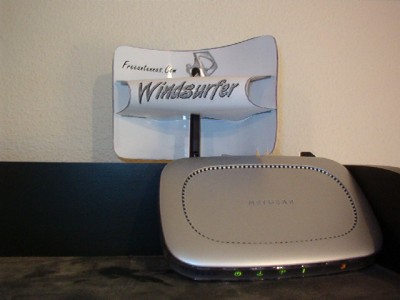
EZ-12, Windsurfer reflector. printed on photo paper for thick stock, with aluminum foil glued to the sail, provides a substantial boost in signal. Leave the tabs longer than on the printout, to make them easier to stick thought the sail.
formatting link
With 54g connections, I find that watching the "current bandwidth" in the Windows perfmon.msc is a pretty good signal indicator. start-run-perfmon.msc + Performance Object = Network Numbers agree with dslreports. + Performance Object = TCP "current bandwidth"
J
Jeff Liebermann
Yeah, I know. It's more expensive than a coffee can.
Oh yes, it's very stiff.
I was thinking of cutting a parabolic template from a 4x6 chunk of lumber and beating the reflect to shape with a rubber mallet. Blacksmithing isn't taught much these days, but it has its uses.
However, I'm going to wait a bit before beating it into a parabola. I wanna see what pattern results from the existing partial cylinderical reflector. I don't expect much in the way of gain or pattern, but it seems like an easy thing to add that doesn't require tools.
Too small. It really should be larger. I'll post the dimensions when I get back home.
Yep. Diversity and two different antenna do not work unless you hide the antennas from each other.
T
TwistyCreek
It's more than I've paid for either of my last two USB g-dongles even!
Ruinous expense! Profligacy!
If there was some way of rolling it into a parabolic arc rather than hammering, it would be better. Surface irregularities supposedly detract greatly from parabolic efficiency. Or so they claim.
I am shocked to see what a gain one can get out of a beat-up, 7" kitchen sieve, though. In my tests with a stationary USB dongle, it shows a measured, graphical increase of 10-12 dBi. Amazing!
Additionally, it keeps access controlled by directing signal toward your rig and not your neighbor's...a not-inconsiderable advantage if he's an ambitious WiFi hacker.
It's 0.062" thick, 4.5" high and 11" around. Too small. It really needs to be at least 6" high to keep the signal from leaking over the edge towards the back of the reflector. Even so, it should have about
6-8dBi gain. I'll do an 4NEC2 model when I have time.
R
Rôgêr
Can't say much for your keyboard mounting arrangement.
J
Jeff Liebermann
Rôgêr hath wroth:
formatting link
clean desk is the sign of a sick mind. A clean house is the sign of a very sick mind.
R
Rôgêr
I must be one of the healthiest people I've ever known then. And that's a scary thought.
W
William P.N. Smith
Nice!
If a cluttered desk is the sign of a cluttered mind, what is an empty desk the sign of?
B
bumtracks
An eBay sellers dream find.
Join the Discussion
Have something to add? Share your thoughts — no account required.
Didn't find your answer?
Ask the community — no account required
Report Content
You are reporting this content to the moderators. They will look at it
ASAP.