Choreboy wrote:
>> A relative has a farm. His phone service comes in on 700 yards
>> of ordinary telephone cable buried along his driveway. Last
>> week he got Bellsouth DSL. It comes in on the same conductors
>> as before, but I've seen speeds fifty times faster than dialup
> And >> Between the CO and the customer, isn't voice service just bare
>> wire?
> Not necessarily. But let's clarify some terminology first.
> I assume that:
> - By "between the CO and the customer," you mean what's
> commonly known as the "local loop."
If only I had remembered the right term!
- By "bare wire" you don't really mean "bare" (as in
> uninsulated); you're simply implying that there's nothing in
> the wirepair, other than copper conductors, that would affect
> the transmission of signals.
Oops, I was thinking "not coaxial" and "bare" popped into my head.
Based on those assumptions, here's an attempt to explain "local loop":
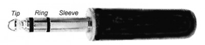
> it's a pair of metallic (usually copper) conductors between the
> customer's premises and the telco's facilities. The conductors are
> designated "ring" and "tip." These terms originated from the physical
> configuration of the plugs used in old manual switchboards. Photo:
>formatting link. Note that the term "ring," as used here,
> does not mean "ringing the telephone."
> The two conductors are usually twisted together, and contained inside
> a cable along with several other wirepairs. At the customer's
> premises, the conductors may run parallel (not twisted) in the drop
> cable from the pole (or pedestal) to the building.
> At the telco's end, the loop may terminate at the CO, or it may
> terminate at a "digital loop carrier remote terminal" (DLCRT, or just
> RT). Telcos often deploy RTs to provide POTS service to outlying
> areas (e.g., new residential neighborhoods or business parks) in order
> to reduce the number and/or length of wirepairs needed to provide
> service to additional customers. Photo:formatting link.
I'll know to look for something the resembles the sermon billboard in front of a church.
Each RT is connected to a host CO, and from the point of view of the
> customer, it's indistinguishable from the CO. POTS lines served from
> the RT are switched at the CO; the RT simply relays signals back and
> forth between the customer and the CO. Numbers are part of the same
> NPA-NXX blocks as the host CO.
Is it indistinguishable if the customer has a V.90 modem? I think I've read that an RT won't allow 56k dialups.
Each RT is connected to its host CO by one or more digital circuits.
> Depending on the number of POTS lines needed, the digital connection
> can be as simple as a single T1 implemented over two copper wirepairs,
> or it can be some multiplexed combination of several T1s implemented
> over coax, fiber, or microwave. Seeformatting link.
Does an RT entail an extra A/D conversion?
Whether or not these digital circuits are part of the "local loop" is
> a matter of some confusion: I've heard it both ways. For the purpose
> of this explanation, I don't include them.
> Now slightly restating the original definition, we can state: the
> local loop consists of two copper conductors between the customer's
> premises and the telco's CO or RT.
> For POTS service, this copper pair carries an amazing number of signals:
> - Balanced baseband analog voice signals in the range
> 300 to 3000 Hz., carried in both directions simultaneously.
> - Audio control signals carried in the same 300-3000 voice
> passband: DTMF signaling tones, dialtone, ring, busy, fault
> tones, etc.
> - DC loop current resulting from a DC bias voltage ("battery")
> applied at the CO or RT. Originally, this current was
> necessary to operate the carbon microphones (or "transmitters"
> as they were called) of older telephones. Modern telephones
> don't use carbon mikes, but they still need DC operating power
> for their transistor or IC circuits. Because this voltage is
> applied directly across the talk circuit, it must be an
> absolutely pure DC voltage (no noise, no ripple). Typical
> battery voltages, applied at the CO or RT, are:
> Tip = ground
> Ring = -48 volts
> - On hook/off hook status, implemented by interrupting the
> DC loop current:
> Loop open = no current = on hook.
> Loop closed = current > 20 ma. = off hook.
> - Rotary-dial pulses, implemented by interrupting the DC loop
> current at specified intervals:
> One pulse = "1"
> Two pulses = "2" etc.
> Ten pulses = "0"
> - Caller ID data, carried as analog data in the voice passband. >
> - Ring voltage to ring the customer's phone. The typical ring
> voltage for a single-party line is 90 volts at 20 Hz,
> asserted across the ring and tip conductors. In party-line
> service, several alternatives have been used:
> Different frequencies (up to about 70 Hz).
> Different connections (tip-to-ground; ring-to-ground)
> Different ring cadences (one long, two short, etc.)
> Combinations of above.
> All of the above signals are carried at frequencies below 4000 Hz.
> Although the voice passband is limited to 300-3000 Hz, the actual
> range of the audio channel extends to 4000 Hz.
> The 3000-Hz cutoff represents the highest frequency necessary for good
> voice communication. That may not be very good by modern hi-fi
> standards, but it's fine for voice.
> Dialup modems (data, fax, home-security, whatever) all utilize this
> same frequency band. There are several modulation schemes floating
> around, but they all do basically the same thing: they modulate the
> data signals onto one or more analog audio carriers, which are then
> carried over the loop in the 300-3000 Hz voice band.
> Every audio signal arriving at the CO (or RT) is digitized at a rate
> of 8000 samples per second before any further switching or
> transmission takes place. This sampling rate is dictated by the
> Nyquist Sampling Theorem, which states that the sampling rate must be
> at least twice the highest frequency being sampled. See
>formatting link
> After sampling, each sample is quantized at one of 256 discrete
> levels, and the resulting value is encoded as an 8-bit binary number.
> The final result is a PCM data stream of 64,000 bits per second. This
> data stream is then transported to the customer's ISP over the PSTN.
> Note that dialup-modem data signals carried in the 300-3000 Hz voice
> passband are not demodulated at the CO or RT; instead, they are
> sampled at 8000 sps just like voice or any other audio signal. This
> fact imposes an absolute theoretical maximum dial-up data rate of
> 64Kbps. As other contributors have noted, it's impossible to attain
> even that rate in practice due to synchronization errors between the
> user's modem and the sampling rate.
A carrier vor V.90 must have some very precise modulation. It's amazing that an 8kHz sampling can capture it well enough to be useful.
Note further that this 4000-Hz limitation is imposed by the CO (or RT)
> equipment, not by the wires themselves. It's possible to use
> frequencies above 4000 Hz for other signals. And that's exactly what
> DSL does. At the CO, a separate piece of equipment, called a "Digital
> Subscriber Line Access Multiplexer" (DSLAM) is connected ahead of the
> voice processing equipment so that it can provide an independent path
> for the DSL signals. Small DSLAMs can be installed in RTs. The DSLAM
> acts as a modem at the telco's end of the loop: it communicates with
> the customer's DSL modem using RF carriers in two frequency bands:
> Uplink (Modem to DSLAM) 30- 110 KHz Downlink (DSLAM to Modem) 110-1100 > KHz
> The DSLAM demodulates uplinked data carriers to recover the original
> data stream. It then sends that data stream to the customer's ISP
> over whatever data link the ISP has installed (which might even be
> another DSL link). For downlink data, the DSLAM accepts data from the
> ISP and modulates it onto a downlink carrier for transmission to the
> customer's DSL modem. The maximum speed is limited by the speed of
> the two data links, the equipment involved, and the policies of the
> telco and the ISP. Images: Large DSLAM for CO installation:
>formatting linkSmall DSLAM for RT installation:
>formatting link
They can bond copper loops to go as high as 27 Mbps!
NOTE THIS DISTINCTION:
> - Dialup modem signals are carried to your ISP over the
> PSTN as a 64Kbps digital representation of the analog
> signal that your dialup modem originally generated.
> - DSL modem signals are carried to your ISP as the actual
> data stream your DSL modem started with.
> Choreboy also asked or commented:
>> Are there inline amps [between the CO and the customer]?
> There are no inline amps, but there are plenty of other things that
> can impair DSL signals (and, for that matter, POTS):
> NOISE. Wirepairs inside a multipair cable are not individually
> shielded (although the cable as a whole may be shielded). Each
> wirepair is twisted so that inductive crosstalk from neighboring
> wirepairs is cancelled out, but some residual crosstalk (particularly
> from other DSL-carrying loops) may not be completely cancelled.
> External signals, such as power-line transients or AM radio station
> carriers, may be inductively coupled into the cable. Drop cables at
> customer premises are usually not shielded; these cables are also
> vulnerable to external noise sources, particularly from nearby
> power-line transients.
Twisting is like low-tech coax. It was advised when using a 300-ohm flat cable from a rooftop TV antenna. I imagine it could help for telephone drop cables.
With one ISP, I kept dropping connections around lunch time. One day I had no trouble. I noticed the mill down the street was closed. The drop line to the guard shack comes from the same aerial terminal as mine. The guard shack would get a lot of calls at lunch time. I wondered if crosstalk from his ring signal was getting me.
All of these noise sources collectively impair the ability of the loop
> to carry DSL signals.
Local loop cables (trunk cables?) seem to deteriorate. Phone men seem to look for available pairs when customers complain of noise. I wonder if voltage from nearby lightning strikes might cause pinhole damage to the insulation of twisted pairs, and over the years it gets hard to find a good pair.
Noise can be mitigated by careful testing to track down noise sources,
> and then by making appropriate repairs. Several manufacturers make
> test equipment for this purpose; seeformatting linkfor an > example.
I used a DMM to check milliamps. My noise came from a spade terminal in the wall jack. I cleaned off the patina and the noise was gone. Low tech!
SIGNAL ATTENUATION. Like any other electrical circuit, telco
> wirepairs comply with a fundamental law of physics: the higher the
> frequency, and/or the longer the wire, the greater the attenuation.
> This situation results from the interaction between the interconductor
> capacitance and the DC resistance of the conductors themselves. Taken
> together, these two parameters cause the wirepair to act like an RC
> circuit (textbooks frequently represent a wirepair as series of lumped
> RC circuits; seeformatting linkfor an example).
> Th is problem can be mitigated by careful selection of transmission
> voltages and by judicious consideration of the tradeoff between loop
> length and transmission speed. Ultimately, however, this situation is
> one reason for the limitation on the length of loops that can be used > for DSL.
> LOAD COILS. The frequency-dependent attenuation characteristics of
> the loop (as described above) also affect voice band frequencies
> (300-3000 Hz), resulting in rolloff of the higher frequencies of voice
> signals. To solve this problem, telcos have traditionally installed
> "load coils" at 6000-foot intervals on long (typically >18K feet)
> loops. A load coil is a small inductor installed across the
> conductors to cancel the affects of interconductor capacitance.
> Although load coils reduce high-frequency rolloff within the voice
> band, they cause severe attenuation above 4000 Hz. See
>formatting link.
At DSL frequencies I would have thought coil impedance would be too high to matter. I don't quite grasp it.
Load coils might be one reason a particular phone sounds distorted at a particular location.
This problem can be resolved by removing the load coils and/or by
> restricting DSL service to loops without load coils. Of course,
> removing the load coils brings back the original problem: rolloff in
> the voice band. Furthermore, any attempt to remove load coils assumes
> that the telco actually knows where they are (anyone who has ever
> worked with telco outside-plant records will recognize the futility of
> that assumption). Appropriate test equipment can be used to determine
> if load coils are present, and to indicate their approximate
> locations.
> BRIDGED TAPS. In a typical telco distribution network, big multipair
> "feeder" cables leave of the CO or the RT, and head off throughout the
> service territory, often along main streets. Smaller (fewer wirepair)
> distribution cables split off from the feeders to serve the customers
> in a "serving area." As the distribution cables pass through the
> serving area, "drop terminals" are installed at intervals. From these
> terminals, drop cables feed individual buildings. A single-family
> home is usually connected by a two- or three-pair drop; larger
> buildings are connected by appropriately larger drop cables.
> In areas where outside plant (OSP) is installed on utility poles,
> telco drop terminals are called "aerial terminals" or "boots";
> typically, a terminal is installed at each pole. Images:
> Aerial terminal:formatting link
That's what somebody pointed out to me as an inline amp. If I could remember who it was, I'd correct him!
Aerial terminal:formatting linkPole with terminal:formatting linkDrawing of interior:formatting linkpage 74 of 77
> In areas where OSP is buried, drop terminals are installed in
> pedestals. In urban areas, telco peds are usually installed in
> easements along rear-property lines. In rural areas, peds are usually
> installed along roadways, at the edge of the right-of-way. Telco peds
> are often placed in "ped clusters" near CATV peds, power peds, and > power transformers.
> Images: Telco ped, closed:formatting linkTelco ped, open:formatting linkPed
> cluster:formatting link
> Each drop terminal has:
> - Two cable ports for the distribution cable: input and output.
> When a drop terminal is installed, these ports are often
> sealed as protection against water intrusion. These seals
> make it virtually impossible to gain access to the individual
> wirepairs within the distribution cable.
As I recall, a phone man appeared to have an aerial terminal open after I lost phone service one day. He said he'd made a mistake and would try to figure out how to reconnect me.
- Several drop ports, one for each wirepair in the distribution
> cable. These ports are usually implemented with screw
> terminals or punchdown blocks.
Across the street, a small trunk line (cable with lots of wire pairs) comes from the aerial terminal down a couple of feet to a fusebox on the utility pole. (I think the telco calls them something besides fuses.) The drop cables come out of that box.
Every wirepair appears at every drop terminal. When a drop is
> installed, the installer connects it to the assigned drop port at the
> nearest terminal; electrically, the drop is bridged across the
> wirepair. But the portion of the wirepair downstream from the bridge
> remains connected, and unterminated at the far end. These
> unterminated downstream wirepairs have come to be known as "bridged > taps."
> These unterminated wirepairs act like tuned-stub filters. Since
> they're unterminated, arriving signals are reflected back; these
> reflected signals interfere with the primary signals. In the extreme
> case -- when the reflected signal is 180 degrees out-of-phase with the
> primary signal -- the primary signal is severely attenuated.
Offhand, that sounds like a stub of 1/4 wavelength. Could the modems could mitigate the problem by the frequency they negotiate?
This problem can only be solved by locating and removing bridged taps.
> This can be an exceedingly difficult job if the distribution cable is
> sealed at that point where it exits the drop terminal.
> Test equipment, such as the Fluke 990formatting link, can be
> used to determine if bridged taps are present, and if so, their
> severity. If the effect of a bridged tap is "minimal" (Fluke's term,
> not mine), it can probably be left in place.
>> Is DSL modulated into some sort of analog signal?
> DSL signals are modulated onto carriers in two bands:
> Uplink (Modem to DSLAM) 30- 110 KHz
> Downlink (DSLAM to Modem) 110-1100 KHz
I wonder how they're modulated.
> It's hard to imagine carrying hig-frequency digital pulses on
>> copper telephone lines.
> Well, T1 circuits do just that. But carrying high-frequency pulses on
> a POTS loop would present a different problem: overlap with the voice > passband.
>> The farm appears to be 35,000 feet from the central office. My
>> browser often shows downloads faster than 1.5 Mb/s (150kB/s).
> If the farm is indeed 35,000 feet from the CO, then I'd have to
> conclude that the loop between the telco and the farm is actually
> connected to a DSLAM-equipped RT, not directly to the CO. Look for a
> large metal box somewhere along the road between the farm and the CO.
> It will have an electric meter; it will probably be set on a concrete
> pad, and it might be surrounded by a security fence.
>> On dialup, the farm couldn't negotiate modem speeds quite as
>> fast as I could in town. I assumed the limitation was in the
>> wire. That's why I was amazed to see that DSL seems to use the
>> wire in the same way as dialup. Was I wrong to think the reason
>> dialup data rates were slower at the farm was that the wire to
>> the CO is longer?
> I'm not sure that it is longer. See previous answer.
>> I don't understand what kind of signal dsl uses to carry so much
>> more data than dialup without needing broadband cable.
> I hope I've answered that question.
>> Ah, crosstalk! It seems to me that if DSL uses the same wire
>> dialup used, the same crosstalk will be present.
> Crosstalk is indeed present, but it's usually only a problem when two
> DSL-carrying loops crosstalk to each other.
>> Does a POTS line from the CO to a house carry multiple
>> voices? Anyway, DSL at the farm uses the same line that
>> the phones at the farm still use.
> In current practice, there's usually just one analog voice channel per > loop.
> Historically, telcos have used various "pair gain" schemes. In one
> scheme, additional voice channels ride on RF carriers superimposed
> across the primary voice channel. Seeformatting link. In
> another scheme, a "phantom" channel is run on two loops, yielding a
> total of three voice channels on two loops. As far as I know, these
> schemes have been phased out by now, but I suppose there might be a
> few still in service somewhere.
> Of course, T1 circuits running on copper are still widely used today.
> Drive down country roads, and you'll often see T1 repeaters spaced at
> (approximately) one-mile intervals. Each T1 can carry 24 voice channels
> over two copper pairs. But a T1 wouldn't normally go to a farm.
> Photo:formatting link.
>> I have trouble understanding on the phone, and I often resort to the
>> phonetic alphabet to be understood. I think the problem may be more
>> in the typical quality of phones than in bandwidth.
> I agree; however, the limited bandwidth is also a factor.
> In a previous life, when I worked for a radio station, we sometimes
> used phone patches for connections to remote locations. At each end,
> we'd connect a "phone patch box" directly to the ring-and-tip of a
> phone line. Then we'd dial up a connection with a conventional phone,
> switch in resistors to keep the line open, and hang up the phones.
> Voice quality wasn't as good as it would have been with a wideband
> audio circuit, but it was certainly far better than it would have been
> if we'd used the telephones themselves. More than adequate for a
> sports or news report.
I wonder if the phone patch box had adjustments to flatten the frequency response. I used to listen to Koss studio headphones (with liquid-filled cushions) plugged into the jack on the front of a stereo. One day it occurred to me that with 220-ohm series resistors, the impedance was too high for 32-ohm phones. I used resistors to make voltage dividers with an output impedance of 1 ohm or so. What a difference!
With a phone line, I guess it's not just a question of impedance. It might need a graphic equalizer.
Of course, making a direct electrical connection to a phone line was
> illegal back in those days (late 50s, early 60s). But we were on good
> terms with the phone guys, so they just looked the other way.
Could you have gone to the federal penitentiary? Was there a good reason for the law?
> If the telco owns the DSLAM, won't their investment cost depend on >> capacity?
> Yes. But the equipment doesn't have to be installed all at once.
> Once the initial investment in the infrastructure (cabinets, racks,
> power supplies, etc.) has been made, circuit cards can be added as
> needed (equipment manufacturers call this approach "scalable"). It's
> the same approach telcos take to POTS.
>> If they contract for the DSLAM service, won't they be charged
>> according to traffic?
> Telcos don't "contract for DSLAM service"; they contract with other
> ISPs (e.g. Covad) who wish to offer their own DSL service over telco
> loops. The telco charges them for the use of their loops. Telco's
> claim they can't charge enough to recover their costs, but that's a
> whole different story -- one that will precipitate a thread even > longer than this one.
>> Think what would have happened if RG-59 hadn't been invented.
>> Everybody would have used RG-6, which looks nearly the same but
>> attenuates uhf much less. With better reception there would have
>> been more uhf stations and less demand for cable.
> As a former cable guy, I don't agree with that. Many UHF stations
> depended on cable TV systems to distribute their signals throughout
> their "specified zones" (which, back in the '60s and '70s, was a
> 35-mile radius around the city of license). This was particularly
> true in mountainous areas where cable T systems carried UHF signals
> to specified-zone communities that were beyond the reach of their > transmitters.
With a bow-tie antenna, a good UHF amp, a rotator, and RG-6U, we could receive so many channels that we weren't interested in cable.
Neal McLain
Thanks, Neal.