A relative has a farm. His phone service comes in on 700 yards
> of ordinary telephone cable buried along his driveway. Last
> week he got Bellsouth DSL. It comes in on the same conductors
> as before, but I've seen speeds fifty times faster than dialup
And > Between the CO and the customer, isn't voice service just bare
wire?
Not necessarily. But let's clarify some terminology first.
I assume that:
- By "between the CO and the customer," you mean what's commonly known as the "local loop."
- By "bare wire" you don't really mean "bare" (as in uninsulated); you're simply implying that there's nothing in the wirepair, other than copper conductors, that would affect the transmission of signals.
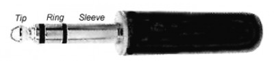
Based on those assumptions, here's an attempt to explain "local loop": it's a pair of metallic (usually copper) conductors between the customer's premises and the telco's facilities. The conductors are designated "ring" and "tip." These terms originated from the physical configuration of the plugs used in old manual switchboards. Photo:
The two conductors are usually twisted together, and contained inside a cable along with several other wirepairs. At the customer's premises, the conductors may run parallel (not twisted) in the drop cable from the pole (or pedestal) to the building.
At the telco's end, the loop may terminate at the CO, or it may terminate at a "digital loop carrier remote terminal" (DLCRT, or just RT). Telcos often deploy RTs to provide POTS service to outlying areas (e.g., new residential neighborhoods or business parks) in order to reduce the number and/or length of wirepairs needed to provide service to additional customers. Photo:
Each RT is connected to a host CO, and from the point of view of the customer, it's indistinguishable from the CO. POTS lines served from the RT are switched at the CO; the RT simply relays signals back and forth between the customer and the CO. Numbers are part of the same NPA-NXX blocks as the host CO.
Each RT is connected to its host CO by one or more digital circuits. Depending on the number of POTS lines needed, the digital connection can be as simple as a single T1 implemented over two copper wirepairs, or it can be some multiplexed combination of several T1s implemented over coax, fiber, or microwave. See
Whether or not these digital circuits are part of the "local loop" is a matter of some confusion: I've heard it both ways. For the purpose of this explanation, I don't include them.
Now slightly restating the original definition, we can state: the local loop consists of two copper conductors between the customer's premises and the telco's CO or RT.
For POTS service, this copper pair carries an amazing number of signals:
- Balanced baseband analog voice signals in the range 300 to 3000 Hz., carried in both directions simultaneously.
- Audio control signals carried in the same 300-3000 voice passband: DTMF signaling tones, dialtone, ring, busy, fault tones, etc.
- DC loop current resulting from a DC bias voltage ("battery") applied at the CO or RT. Originally, this current was necessary to operate the carbon microphones (or "transmitters" as they were called) of older telephones. Modern telephones don't use carbon mikes, but they still need DC operating power for their transistor or IC circuits. Because this voltage is applied directly across the talk circuit, it must be an absolutely pure DC voltage (no noise, no ripple). Typical battery voltages, applied at the CO or RT, are: Tip = ground Ring = -48 volts
- On hook/off hook status, implemented by interrupting the DC loop current: Loop open = no current = on hook. Loop closed = current > 20 ma. = off hook.
- Rotary-dial pulses, implemented by interrupting the DC loop current at specified intervals: One pulse = "1" Two pulses = "2" etc. Ten pulses = "0"
- Caller ID data, carried as analog data in the voice passband.
- Ring voltage to ring the customer's phone. The typical ring voltage for a single-party line is 90 volts at 20 Hz, asserted across the ring and tip conductors. In party-line service, several alternatives have been used: Different frequencies (up to about 70 Hz). Different connections (tip-to-ground; ring-to-ground) Different ring cadences (one long, two short, etc.) Combinations of above.
All of the above signals are carried at frequencies below 4000 Hz. Although the voice passband is limited to 300-3000 Hz, the actual range of the audio channel extends to 4000 Hz.
The 3000-Hz cutoff represents the highest frequency necessary for good voice communication. That may not be very good by modern hi-fi standards, but it's fine for voice.
Dialup modems (data, fax, home-security, whatever) all utilize this same frequency band. There are several modulation schemes floating around, but they all do basically the same thing: they modulate the data signals onto one or more analog audio carriers, which are then carried over the loop in the 300-3000 Hz voice band.
Every audio signal arriving at the CO (or RT) is digitized at a rate of 8000 samples per second before any further switching or transmission takes place. This sampling rate is dictated by the Nyquist Sampling Theorem, which states that the sampling rate must be at least twice the highest frequency being sampled. See
Note that dialup-modem data signals carried in the 300-3000 Hz voice passband are not demodulated at the CO or RT; instead, they are sampled at 8000 sps just like voice or any other audio signal. This fact imposes an absolute theoretical maximum dial-up data rate of
64Kbps. As other contributors have noted, it's impossible to attain even that rate in practice due to synchronization errors between the user's modem and the sampling rate.
Note further that this 4000-Hz limitation is imposed by the CO (or RT) equipment, not by the wires themselves. It's possible to use frequencies above 4000 Hz for other signals. And that's exactly what DSL does. At the CO, a separate piece of equipment, called a "Digital Subscriber Line Access Multiplexer" (DSLAM) is connected ahead of the voice processing equipment so that it can provide an independent path for the DSL signals. Small DSLAMs can be installed in RTs. The DSLAM acts as a modem at the telco's end of the loop: it communicates with the customer's DSL modem using RF carriers in two frequency bands: Uplink (Modem to DSLAM) 30- 110 KHz Downlink (DSLAM to Modem) 110-1100 KHz
The DSLAM demodulates uplinked data carriers to recover the original data stream. It then sends that data stream to the customer's ISP over whatever data link the ISP has installed (which might even be another DSL link). For downlink data, the DSLAM accepts data from the ISP and modulates it onto a downlink carrier for transmission to the customer's DSL modem. The maximum speed is limited by the speed of the two data links, the equipment involved, and the policies of the telco and the ISP. Images: Large DSLAM for CO installation:
- Dialup modem signals are carried to your ISP over the PSTN as a 64Kbps digital representation of the analog signal that your dialup modem originally generated.
- DSL modem signals are carried to your ISP as the actual data stream your DSL modem started with.
Choreboy also asked or commented:
Are there inline amps [between the CO and the customer]?
There are no inline amps, but there are plenty of other things that can impair DSL signals (and, for that matter, POTS):
NOISE. Wirepairs inside a multipair cable are not individually shielded (although the cable as a whole may be shielded). Each wirepair is twisted so that inductive crosstalk from neighboring wirepairs is cancelled out, but some residual crosstalk (particularly from other DSL-carrying loops) may not be completely cancelled. External signals, such as power-line transients or AM radio station carriers, may be inductively coupled into the cable. Drop cables at customer premises are usually not shielded; these cables are also vulnerable to external noise sources, particularly from nearby power-line transients.
All of these noise sources collectively impair the ability of the loop to carry DSL signals.
Noise can be mitigated by careful testing to track down noise sources, and then by making appropriate repairs. Several manufacturers make test equipment for this purpose; see
SIGNAL ATTENUATION. Like any other electrical circuit, telco wirepairs comply with a fundamental law of physics: the higher the frequency, and/or the longer the wire, the greater the attenuation. This situation results from the interaction between the interconductor capacitance and the DC resistance of the conductors themselves. Taken together, these two parameters cause the wirepair to act like an RC circuit (textbooks frequently represent a wirepair as series of lumped RC circuits; see
This problem can be mitigated by careful selection of transmission voltages and by judicious consideration of the tradeoff between loop length and transmission speed. Ultimately, however, this situation is one reason for the limitation on the length of loops that can be used for DSL.
LOAD COILS. The frequency-dependent attenuation characteristics of the loop (as described above) also affect voice band frequencies (300-3000 Hz), resulting in rolloff of the higher frequencies of voice signals. To solve this problem, telcos have traditionally installed "load coils" at 6000-foot intervals on long (typically >18K feet) loops. A load coil is a small inductor installed across the conductors to cancel the affects of interconductor capacitance. Although load coils reduce high-frequency rolloff within the voice band, they cause severe attenuation above 4000 Hz. See
This problem can be resolved by removing the load coils and/or by restricting DSL service to loops without load coils. Of course, removing the load coils brings back the original problem: rolloff in the voice band. Furthermore, any attempt to remove load coils assumes that the telco actually knows where they are (anyone who has ever worked with telco outside-plant records will recognize the futility of that assumption). Appropriate test equipment can be used to determine if load coils are present, and to indicate their approximate locations.
BRIDGED TAPS. In a typical telco distribution network, big multipair "feeder" cables leave of the CO or the RT, and head off throughout the service territory, often along main streets. Smaller (fewer wirepair) distribution cables split off from the feeders to serve the customers in a "serving area." As the distribution cables pass through the serving area, "drop terminals" are installed at intervals. From these terminals, drop cables feed individual buildings. A single-family home is usually connected by a two- or three-pair drop; larger buildings are connected by appropriately larger drop cables.
In areas where outside plant (OSP) is installed on utility poles, telco drop terminals are called "aerial terminals" or "boots"; typically, a terminal is installed at each pole. Images:
Aerial terminal:
In areas where OSP is buried, drop terminals are installed in pedestals. In urban areas, telco peds are usually installed in easements along rear-property lines. In rural areas, peds are usually installed along roadways, at the edge of the right-of-way. Telco peds are often placed in "ped clusters" near CATV peds, power peds, and power transformers.
Images: Telco ped, closed:
- Two cable ports for the distribution cable: input and output. When a drop terminal is installed, these ports are often sealed as protection against water intrusion. These seals make it virtually impossible to gain access to the individual wirepairs within the distribution cable.
- Several drop ports, one for each wirepair in the distribution cable. These ports are usually implemented with screw terminals or punchdown blocks.
Every wirepair appears at every drop terminal. When a drop is installed, the installer connects it to the assigned drop port at the nearest terminal; electrically, the drop is bridged across the wirepair. But the portion of the wirepair downstream from the bridge remains connected, and unterminated at the far end. These unterminated downstream wirepairs have come to be known as "bridged taps."
These unterminated wirepairs act like tuned-stub filters. Since they're unterminated, arriving signals are reflected back; these reflected signals interfere with the primary signals. In the extreme case -- when the reflected signal is 180 degrees out-of-phase with the primary signal -- the primary signal is severely attenuated.
This problem can only be solved by locating and removing bridged taps. This can be an exceedingly difficult job if the distribution cable is sealed at that point where it exits the drop terminal.
Test equipment, such as the Fluke 990
Is DSL modulated into some sort of analog signal?
DSL signals are modulated onto carriers in two bands: Uplink (Modem to DSLAM) 30- 110 KHz Downlink (DSLAM to Modem) 110-1100 KHz
It's hard to imagine carrying hig-frequency digital pulses on
> copper telephone lines.
Well, T1 circuits do just that. But carrying high-frequency pulses on a POTS loop would present a different problem: overlap with the voice passband.
The farm appears to be 35,000 feet from the central office. My
> browser often shows downloads faster than 1.5 Mb/s (150kB/s).
If the farm is indeed 35,000 feet from the CO, then I'd have to conclude that the loop between the telco and the farm is actually connected to a DSLAM-equipped RT, not directly to the CO. Look for a large metal box somewhere along the road between the farm and the CO. It will have an electric meter; it will probably be set on a concrete pad, and it might be surrounded by a security fence.
On dialup, the farm couldn't negotiate modem speeds quite as
> fast as I could in town. I assumed the limitation was in the
> wire. That's why I was amazed to see that DSL seems to use the
> wire in the same way as dialup. Was I wrong to think the reason
> dialup data rates were slower at the farm was that the wire to
> the CO is longer?
I'm not sure that it is longer. See previous answer.
I don't understand what kind of signal dsl uses to carry so much
> more data than dialup without needing broadband cable.
I hope I've answered that question.
Ah, crosstalk! It seems to me that if DSL uses the same wire
> dialup used, the same crosstalk will be present.
Crosstalk is indeed present, but it's usually only a problem when two DSL-carrying loops crosstalk to each other.
Does a POTS line from the CO to a house carry multiple
> voices? Anyway, DSL at the farm uses the same line that
> the phones at the farm still use.
In current practice, there's usually just one analog voice channel per loop.
Historically, telcos have used various "pair gain" schemes. In one scheme, additional voice channels ride on RF carriers superimposed across the primary voice channel. See
Of course, T1 circuits running on copper are still widely used today. Drive down country roads, and you'll often see T1 repeaters spaced at (approximately) one-mile intervals. Each T1 can carry 24 voice channels over two copper pairs. But a T1 wouldn't normally go to a farm. Photo:
I have trouble understanding on the phone, and I often resort to the
> phonetic alphabet to be understood. I think the problem may be more
> in the typical quality of phones than in bandwidth.
I agree; however, the limited bandwidth is also a factor.
In a previous life, when I worked for a radio station, we sometimes used phone patches for connections to remote locations. At each end, we'd connect a "phone patch box" directly to the ring-and-tip of a phone line. Then we'd dial up a connection with a conventional phone, switch in resistors to keep the line open, and hang up the phones. Voice quality wasn't as good as it would have been with a wideband audio circuit, but it was certainly far better than it would have been if we'd used the telephones themselves. More than adequate for a sports or news report.
Of course, making a direct electrical connection to a phone line was illegal back in those days (late 50s, early 60s). But we were on good terms with the phone guys, so they just looked the other way.
If the telco owns the DSLAM, won't their investment
> cost depend on capacity?
Yes. But the equipment doesn't have to be installed all at once. Once the initial investment in the infrastructure (cabinets, racks, power supplies, etc.) has been made, circuit cards can be added as needed (equipment manufacturers call this approach "scalable"). It's the same approach telcos take to POTS.
If they contract for the DSLAM service, won't they be charged
> according to traffic?
Telcos don't "contract for DSLAM service"; they contract with other ISPs (e.g. Covad) who wish to offer their own DSL service over telco loops. The telco charges them for the use of their loops. Telco's claim they can't charge enough to recover their costs, but that's a whole different story -- one that will precipitate a thread even longer than this one.
Think what would have happened if RG-59 hadn't been invented.
> Everybody would have used RG-6, which looks nearly the same but
> attenuates uhf much less. With better reception there would have
> been more uhf stations and less demand for cable.
As a former cable guy, I don't agree with that. Many UHF stations depended on cable TV systems to distribute their signals throughout their "specified zones" (which, back in the '60s and '70s, was a
35-mile radius around the city of license). This was particularly true in mountainous areas where cable TV systems carried UHF signals to specified-zone communities that were beyond the reach of their transmitters.
Neal McLain