100BASE-TX is said by a number of authors to have its fundamental frequency at 31.25 MHz, but the proofs given (if any) seem vague or questionable at best. E.g., I think I met a proof going as follows: There are four elements in the cycle through which the signal level loops in MLT-3, so the main clock of 125 MHz is divided by 4.
An amateur in data communications, the only pseudo-scientific speculation I could put together is as follows: MLT-3 acts as a four-state line code, perhaps due to its cycle length: {-1, 0, +1, 0}. Therefore by Hartley's law its effective symbol rate in 100BASE-TX is 125 Mbit/s / log2(4) = 62.5 Mbaud. And now by the sampling theorem we get to the fundamental frequency of 62.5 / 2 = 31.25 MHz. What I cannot prove here is MLT-3's being a four-state code.
Do you think my speculation makes any sense? And if so, do you have any ideas on how to ground this apparent alphabet size of MLT-3? Thanks!
Didn't find your answer? Ask the community — no account required.
A
Albert Manfredi
The worst case for MLT-3 is to encode a series of 1 bits. That creates the most transitions of state, since each 1 bit creates a transition. What a series of 1s encodes into, with MLT-3, is a transition from -1 to 0 to +1 to 0, then back to -1.
So if you totally ignore the sharp edges, this creates a complete (negative) cosine cycle to represent 4 bits of data, worst case. Think of this MLT-3 wave shape being heavily low-passed filtered, removing all the edges.
The next consideration is that in 100BASE-TX (and FDDI), the bits are encoded as 4B/5B, which means 5 bits for every 4 data-carrying bits. So the worst case for 100BASE-TX would be a series of 1 bits transmitted at a baud rate of 125 Mbaud.
If you transmit 125 Mbaud encoded as MLT-3, you will therefore create a sinusoid 125/4 =3D 31.25 Mcycles/sec, if you pass the signal through a low-pass filter that removes all the sharp edges. So that is the fundamental frequency you would see in a spectrum analyzer, worst case (series of 1 bits created by the 4B/5B code).
However, note that in the above, there is no consideration of whether or not that signal will be decodable as received. It's only an explanation of the fundamental frequency generated, worst case. That's all. If the signal is "strong enough," or undistorted enough, whatever that means in a given case, it will be decodable.
Hartley's law does indeed say the bandiwdth required, minimum, to transmit 125 Mbaud is 31.25 MHz, but ONLY if you set M to 4, as you did.
M =3D 1 + (V / voltage resolution of receiver)
where the signal voltage transitions from -V to +V.
By setting M to 4, you are saying that in order for the receiver to be able to decode accurately this 31.25 MHz signal, the voltage detection resolution of the receiver must be at least good enough to be able to detect a difference in received voltage 1/3 as great as the total voltage transitions seen in this incoming signal.
So take an example of a receiver only capable of detecting a voltage difference that's 1/2 as great as the incoming signal voltage transitions, and it will not be able to correctly decode the 125 Mbaud signal.
Bert
G
glen herrmannsfeldt
The fastest it can go through a full cycle is 125MHz/4. Assuming you filter it properly, other patterns will result in lower frequencies. To really understand it you need to know where the sidebands are. As usual, that is where the information is stored.
If you really want to know, do a Fourier transform of the result with random bits (approximating that out of the scrambler).
Following one of Shannon's laws, it trades off frequency (bandwidth) against signal/noise. For a given amplitude, the noise required to miss a transition is smaller than with a simpler code.
-- glen
Y
Yar Tikhiy
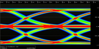
This is a nice picture to grasp the problem intuitively, thank you!
The Message-ID was:
The Google Groups URL:
formatting link
And from what Rich said follows M = 2^2 = 4. Therefore I'm not the only one to set the M to 4. :-)
Excuse me, but I don't quite follow you here. Why such a receiver won't be able to decode the signal?
To detect a basic MLT-3 transition, such as 0 -> +V, the receiver needs resolution of +-V/2. The overall voltage range is -V..+V. Therefore Hartley's equation for M yields: M = 1 + (V / (V/2)) = = 1 + 2 = 3, which makes sense as MLT-3 indeed has 3 output levels.
However, as far as I can tell, Hartley assumed the simple model of an M-state semaphore where a transition to any of the M states is allowed irrespective of the history, whereas MLT-3 cannot produce transitions like +V -> -V or -V -> +V; moreover, transition pairs like -V -> 0 -> -V or +V -> 0 -> +V cannot happen either. Thus MLT-3 doesn't fit Hartley's model readily; it isn't a plain vanilla ternary code conveying log2(3) information bits per code symbol.
G
glen herrmannsfeldt
There are four transitions, 0 to +1, to 0, to -1, and back to 0.
formatting link
Yes, specifically all the information is in the sidebands not in the carrier itself. To really answer the question, one should compare against some other possible encodings.
For ethernet, traditionally it was manchester coding, (or synchronous phase modulation if you like that better). Manchester is inefficient, but makes clock recovery easy.
More efficient would be NRZ or NRZI, with a scrambler to ensure sufficient transitions for good clock recovery. These have a fundamental frequency at half the transition (bit) rate.
As indicated, MLT-3 has a fundamental of one quarter the bit rate.
The fundamental is most important when considering RFI effects. The sidebands when designing filters and considering the ability to decode the bits. The sideband spectra of the different codings can be very different.
-- glen
A
Albert Manfredi
True, but these transitions bring you to three states. Or are you saying that the four transitions would make M=3D4 in the Hartley law? Could be. I'm not sure about this, now that you mention it.
Well, this highest fundamental frequency is actually what creates the widest sideband. This MLT-3 is a baseband signal, centered on 0 Hz. So by figuring out the highest possible fundamental, we should get an idea of how wide the most meaningful part of the spectrum is going to be. Above and below this, the spectrum should drop off fairly quickly.
But because we're talking about a baseband signal here, this "fundamental" that we've fussed about is only one of 2^5 possible (one for each 5-bit pattern of 4B/5B), if you view MLT-3 on a spectrum analyzer. This is the "fundamental" that creates the main peak at the edges of the MLT-3 spectrum. For any other bit pattern possible in
100BASE-TX, you'll see other "fundamentals" much like this one, only closer in to 0 Hz.
Also, Shannon doesn't care about this M value of Harltey's law, but it instead shows the tradeoff between SNR required vs. how spectrally "efficient" the coding scheme is.
So, for example, Shannon says that using a 39 MHz channel for 125 Mbaud bit rate is quite robust. It only requires 9.15 dB of SNR, at the limit (assuming perfect error correction). Not bad. Quite good even for radio transmission.
On the other hand, if you could guarantee a nice hefty 40 dB of SNR, you could use some better scheme than MLT-3, and you'd only need 9.4 MHz of bandwidth for transferring the 125 Mbaud of 100BASE Ethernet.
Bert
Y
Yar Tikhiy
Signal polarity should be irrelevant to differential line codes, so the sequence {-1, 0, +1, 0, -1} isn't really different from {0, +1, 0, -1, 0}. Thus you and Albert were talking about essentially the same thing. :-)
In my case, I just tried to use the nice value of the fundamental frequency of 100BASE-TX as a key to this concept, which isn't intuitive by itself: "[...] MLT-3 encoding [...] has a maximum of one transition for every two code-bits." [1] But the bottom line here seems to be that MLT-3 apparently having one transition for every two code-bits is a mere speculation based on the fundamental frequency value, and not the other way around. It's unlike with Manchester code, when one can start from its notion, then easily deduce its baud rate for a given data rate, and finally predict the signal's fundamental frequency via the sampling theorem.
Thank you all for the interesting discussion!
References: [1]
formatting link
G
glen herrmannsfeldt
(snip)
The best way I can think of to do this is to actually look at the spectrum from a random bit stream. Assuming a good scrambler, the output bit stream should be pretty close to random.
Using R, it is pretty easy to generate a random data stream and plot the results.
formatting link
For the NRZ case, generate a random array of 0s and 1s, and take abs(fft(bits)). Then plot() the result, and it looks very flat.
x0.5 plot(abs(fft(x)))
The Manchester spectrum peaks at the bit rate (half the clock rate).
xx
A
Albert Manfredi
Cool.
That makes sense. NRZ creates a random number of transitions when transferring random data patterns, and NRZ can result in a long string with no transitions if the data bits are a string of 0s or 1s. So you'd expect a flat spectrum with random input.
Manchester creates one transition per bit, no matter what. So you would not expect the energy to be distributed down to 0 Hz. I would have expected a pattern 010101 ... to create a fundamental at half the bit rate, and a pattern 1111.... or 0000.... to create a fundamental at the bit rate. So a random pattern ought to result in the energy distributed evenly in the range between half the bit rate and the bit rate. Hmmm.
And MLT-3 should create a large number of fundamentals below that
31.25 MHz highest one we've been discussing(string of 1 bits), so you wouldn't expect the peak for a random bit pattern to be anywhere close to 31.25 MHz.
So the only one that seems strange to me is the Manchester result.
Bert
G
glen herrmannsfeldt
Albert Manfredi wrote: (snip)
You can see that below half the bit rate it should fall off pretty fast. The 0101010101 pattern is pretty special, though. The reason to do the calculation was that it wasn't so obvious to me.
Also, I believe that Manchester ethernet doesn't use a scrambler so the data patterns might not be so random.
-- glen
Join the Discussion
Have something to add? Share your thoughts — no account required.
Didn't find your answer?
Ask the community — no account required
Report Content
You are reporting this content to the moderators. They will look at it
ASAP.