A while back I had a slightly OT discussion regarding the practicalities of fractal antennas for HDTV.
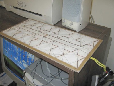
I subsequently made an 8 element version and it works very well in areas of no line of sight/poor reception.
I don't use a reflector on this and it's interesting that the antenna works well on both the horizontal and vertical plane indoors.
See below using on the horizontal.
formatting link
So any insight into which plane is optimum for this type of design ?
I was quite surprised that it works in the alignment seen in the picture.
Could it be used as a beam antenna with a suitable reflector at one end ?
Maybe it's just picking up a reflected/multipath signal from the metal roof ?
Didn't find your answer? Ask the community — no account required.
A
atec77
fractal antennas for HDTV.
line of sight/poor reception.
well on both the horizontal and vertical plane indoors.
Have you fiddled with it near an rf source watching signal ??
D
Dr Who
fractal antennas for HDTV.
no line of sight/poor reception.
well on both the horizontal and vertical plane indoors.
If I go outside it gets swamped with signal and there's no discernable difference between antenna orientation.
But using it indoors with no line of site and very bad reception conditions it's interesting that it works better on the horizontal plane than the vertical.
So getting back to my original question, could this type of array be used as a beam antenna ?
M
miso
of fractal antennas for HDTV.
of no line of sight/poor reception.
ks well on both the horizontal and vertical plane indoors.
You should model it in NEC2.
D
Dr Who
fractal antennas for HDTV.
no line of sight/poor reception.
well on both the horizontal and vertical plane indoors.
Good thinking.
I will have a go tonight.
J
Jeff Liebermann
Common commercial HDTV antenna models:
Note: You're really asking this in the wrong newsgroup. Look for something that discusses TV antenna.
formatting link
would probably be a good place to start.
D
Dr Who
Thanks for the links Jeff.
I posted it here just as a discussion on fractal antennas per se.
I will check out the avsforum. I wasn't aware of that one.
Cheers
J
Jeff Liebermann
Oops. Wrong URL:
Antenna discussions usually land in HDTV technical:
I didn't find anything specific on fractal antennas, but did find this
100+ thread on UHF TV construction:
I can't resist offering my never humble opinion on fractal antennas. Methinks they only make sense when dealing with a specialized radiation pattern (i.e. cell phone SAR) in a confined area (i.e. inside a cell phone) such as a box. When there are few limits on the size of the antenna, such as in an outdoor antenna, fractal antennas are not the best solution.
Basically, it's compromise between size, gain, and bandwidth. You can have any two, at the expense of the third. For example, the gain of a simple dipole is about 2.1dBi. If you shrink the length of each element, the gain remains about 2dBi until you get down to about
1/10th wavelenth. Of course, the tuning also changes, so you have to add inductance (loading coils) to tune it, and a matching circuit to reduce losses. Both of those drastically reduce the bandwidth of the antenna. So, you keep your gain, reduce the size, but screw up the bandwidth. That's not a good idea for a TV antenna, which needs plenty of bandwidth.
I suggest you use 4NEC2 to model a simple dipole. Then change it to a simple fractal dipole per your photo and compare the results. When you model your completed antenna, compare it with the other similar size HD antennas that I previously posted links. At some frequency, your fractal antenna will probably have the same gain, be smaller, and have a narrower bandwidth, so that it only works on some partial range of TV channels.
A
AES
Can fractal antennas solve the problem of the Penrose Unilluminable Room? [Smiley attached here]
Drag the little omnidirectional light bulb around inside the room.
D
Dr Who
Thanks again Jeff.
The thing that shocked me was that the fractal antenna worked so well laying on it's back pointing upwards towards the sky. I only discovered this by accident.
Up until then I had viewed it as a directinal panel antenna for Digital TV application and that it would be orientated on the vertical like a biquad.
Any reflector that is added seems to be also aligned in a similar fashion to a biquad. But as the fractal is used extensively as a patch antenna in mobile phones, I suppose element orientation isn't an issue.
That being the case it might be possible to use a reflector in a different alignment - eg. at the end of the array.
I will try and see if I can find a schematic of a fractal dispersion pattern.
Cheers
Cheers
M
miso
As you shrink the antenna, the aperture also decreases. That is, your antenna sits in a RF field, and the less area you occupy, the less RF you get at the antenna terminal.
I will admit I have a hard time getting around the notion of antenna aperture. However, if you look at the telescope analog, it makes more sense. Think of gain is magnification, and aperture as the light gathering ability. For any one setting of magnification, you can have any amount of light coming out the ocular. Compare binocs with 50mm objectives versus 20mm objectives. Same magnification, but one puts out less light. At some point the light output is beneath what is useful.
In ham land, lower frequency goes further tends to be the rule. But if we stay away from ionospheric effects, as you go lower, for the same gain, the antenna is getting larger, hence more aperture.
The wiki is kind of OK regarding aperture.
formatting link
I don't like how they tightly correlate gain to aperture. Compare a pyramidal horn to a dish. If you could deal with the size, a horn and dish could have the same aperture, but I think the dish would have to be more directional. I'm not totally sure about them. But if you look at those amateur SETI setups, many use big ass pyramidal horns pointing straight up so as to not get too directional.
formatting link
I'd like to have this kind of person as my neighbor. Except I'd encourage the guy to make a bigger antenna. As you know, the FCC rule allow any CONUS homeowner to have any number of 1 meter dishes, but I'm not so sure your right to a big ass horn is a done deal.
J
Jeff Liebermann
I had to install the CDF player (100 MBytes) before that would work. I don't own Mathematica.
I then found that the resultant shadows were really rather large granular regions, instead of ray tracing the shadows. Still, I can see how it works and yes, there will always be a shadow region. I could probably do the same with a labyrinth, but that doesn't count.
I don't see what a fractal could do for the problem. The light source is defined as a point source and isotropic in the original problem. A fractal version of the light would look like umm... a point source. No change there. On the other foot, a fractal room would probably look like something designed by M.C. Escher and have areas located in other dimensions or hyperspace. Great science fiction stuff, but not very useful.
D
Dr Who
He looks pretty happy with his rig.
I detect a look in his eye that says, "and now for something bigger".
W
Warren Oates
And He Built a Crooked House!
formatting link
J
Jeff Liebermann
SETI horns:
I like these old horn photo:
Incidentally, RF horns are not the only types. There's also acoustic horns, used before the introduction of radar.
J
Jeff Liebermann
Sorry. Old web site. This is the current version with more photos:
\
D
Dr Who
Ha Ha those photos are classic.
Never seen those rigs before.
I hate to think what would happen to the poor operator if a cannon went off nearby or a flock of screeching birds flew through it's path.
Burst eardrums I expect.
Good one.
M
miso
Well I never knew they tried acoustic location. Of course Radar from MASH was pretty good at hearing distance choppers. Then again, I suspect he was tipped off by the radio dude in the comm shack.
I've read some of Douglass Self's papers. If anything, he tends to be an audio foolery debunker. However, I haven't read any of his books.
There is a horn design program floating around the net. Freakin' dos. I had to run it in dosbox. All that stuff is on a different PC that I'm backing up at the moment. Horn antennas, being based on aperture, probably work better in real life construction than say a yagi. It is tough to cut and space yagi elements to exacting dimensions. But if you play with the spreadsheet to simulate horn gain, you can screw up a lot and not change the gain too much. Plus they are very broadband.
Gain analysis: avsport.org/microcomm/software/horngain.xls
Here again you are gaining aperture and gain at the same time.
And for more entertainment, the fly swatter antenna:
formatting link
A
AES
Jeff,
These are some superb links to the early history of radio astronomy, horn antennas, the 21 cm hydrogen line, and early technology in general; and also starting points for a lot of additional sources.
The third of these links eventually leads to a photo of Harold Ewen as a grad student, and his hydrogen line apparatus on the fourth floor of the Lyman Lab at Harvard:
and this in turn brings back a personal memory for me, which I might as well set down for my own historical notes, if nothing else.
As a very young and naive major in "ESAP" (Engineering Science and Applied Physics} I took a lab course in electromagnetism that was taught in a student lab on an upper floor of Lyman sometime between Autumn 1949 and June 1952, during which I noted this odd vertical horn on the roof or parapet just outside one of the lab windows. I don't recall it as being very large, and I think I initially tok it to be some kind of rainfall collection device.
During these afternoon lab sessions, which must have been held in either the room this photo was taken in or one very closely adjacent, my lab partner and I measured things like how the resonant response of two coupled audio resonant circuits formed from big clunky capacitors and iron inductors changed and split as you detuned their resonance frequencies or moved the inductors closer to each other.
During one of these sessions we also noticed this slightly older guy climbing in and out the window onto the roof and messing with this horn; and my lab partner asked him what he was doing with it. I quite clearly recall him saying something very much like, "Oh, I'm watching hydrogen molecules flip over out in space."
It was only several decades later that I realized that "this guy" must have been "Doc" Ewen, and the horn must have been part of his hydrogen line experiment (or at least some immediate predecessor to it).
J
Jeff Liebermann
You might also find this interview of interest:
Well, at least it wasn't "natural philosophy". I didn't think you were that old.
Incidentally, I majored in "Electrical and Electronic Engineering" which was rather appropriate as neither the administration, faculty, or students could distinguish between them. I learned the most about electronics in the calibration lab, repairing the damage inflicted upon the instruments by the students.
I read somewhere that the unofficial description was a "coal hopper" or something similar.
I built a similar size device in jr high skool out of plywood and aluminum foil. The intended purpose was to measure the RF level produced by the sun at about 1.4GHz. It should have been a no-brainer, but we kept blowing up 1N21 mixer diodes with ESD. Years later, I calculated and later measured the front end noise figure of the excessively wide-band radar IF receiver I was using for this test at about 3000K. Oops. It was also lots of fun trying to track the sun with this monstrosity. This was somewhat after Sputnik was launched, and our efforts received a page two photo and story in the papers as "young students advancing science". I'll see if I can find some old photos.
Join the Discussion
Have something to add? Share your thoughts — no account required.
Didn't find your answer?
Ask the community — no account required
Report Content
You are reporting this content to the moderators. They will look at it
ASAP.